
Figure 1.12. Configuration of a rectangular waveguide.
There are two sets of wave modes, TE and TM modes, that can propagate in a rectangular waveguide as shown in Fig.1.12. For the TE modes, Ez = 0, and the Hz component takes the form Hz = A cos kx x cos ky y e -j kz z. Substituting this into the wave equation gives the dispersion relation kx2 + ky2 + kz2 = ω2 μ ε. The other field components can be derived from (1.29) and (1.30).

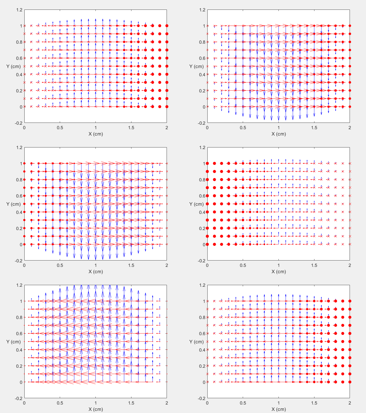
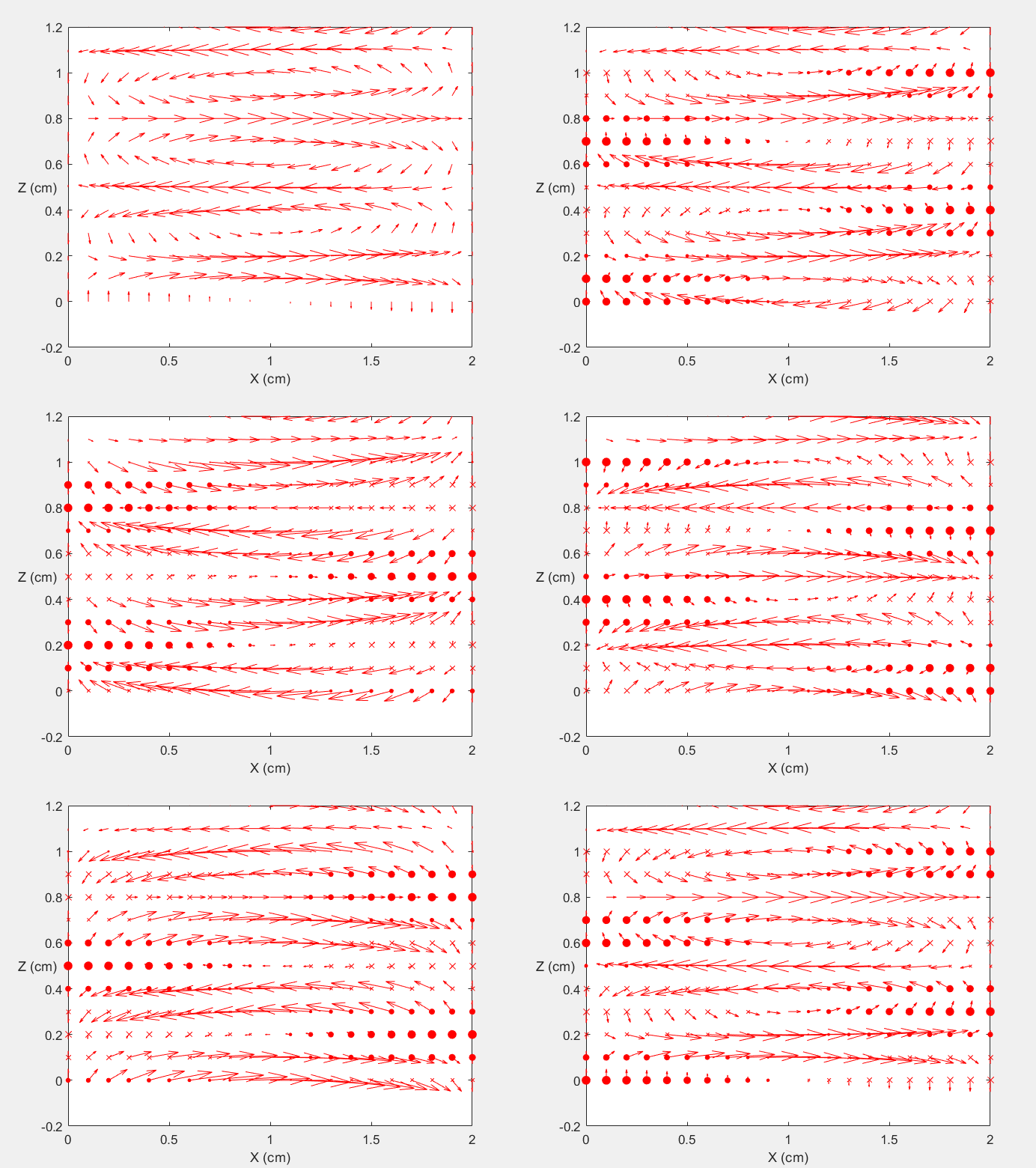
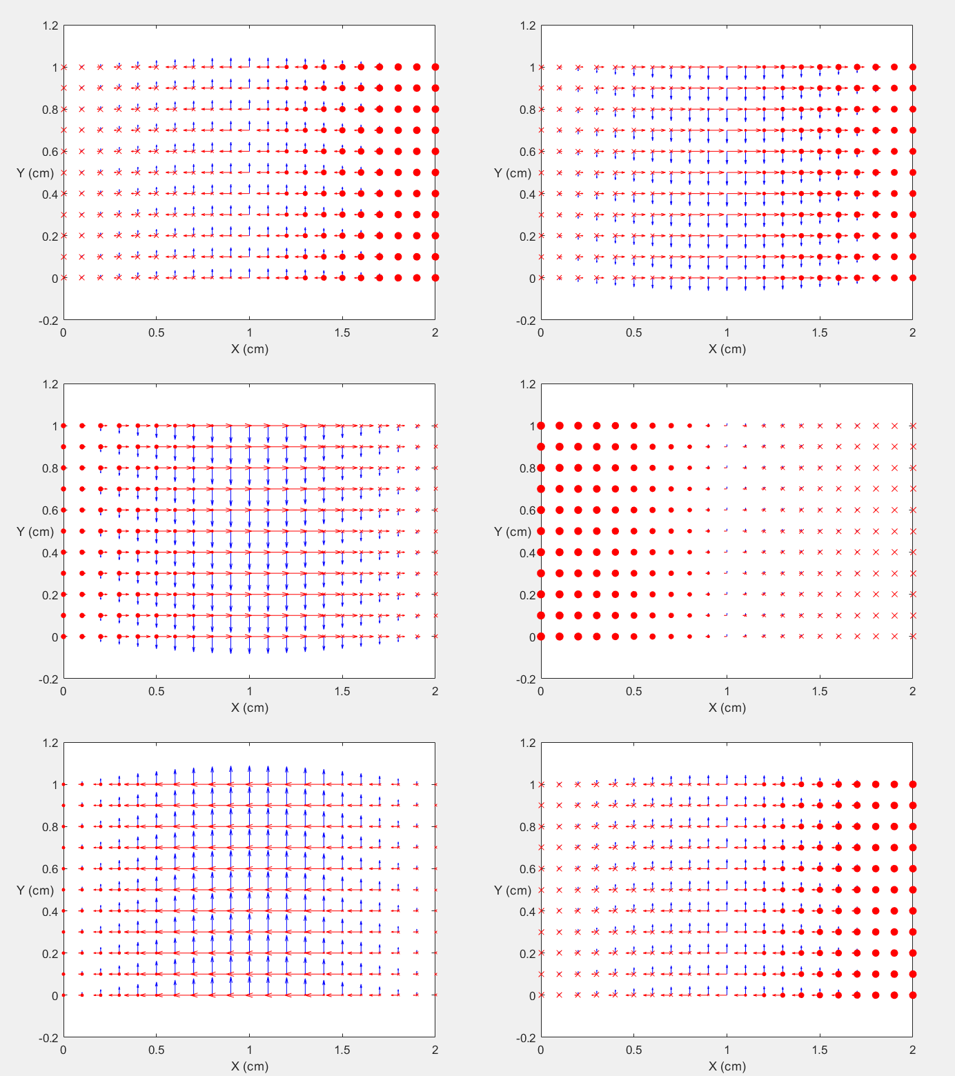
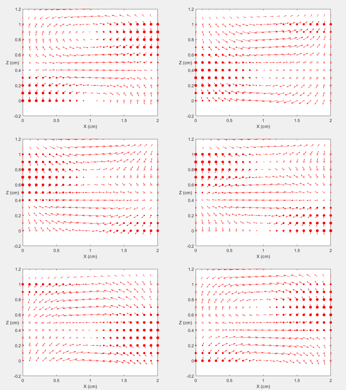
The boundary conditions require that Ex = 0 at y = 0 and y = b, Ey = 0 at x = 0 and x = a. Hence, two sets of guidance conditions are obtained as kx = m π / a and ky = n π / b, and where m, n = 0, 1, 2,… but m2 + n2 ≠ 0. The TE mode with kx = m π / a and ky = n π / b, is called the TEmn mode. Most practical waveguides operate in the TE10 mode where kz = √ ω2με - (π / a)2 , the cutoff wave number is kc = π/a, the cutoff wavelength is λc = 2a, and the electric field is Ē = ŷ Eo sin(π x / a) e -j kz z.
Similarly, the TM modes can be derived by assuming Hz = 0 and Ez = A sin kx x sin ky y e -j kz z. The same form of guidance conditions is obtained except that m, n = 1, 2, … .
Table 1. Field Expressions and Associated Parameters for TE Mode in a Rectangular Waveguide
|
Ēz = 0 Ēx = j λc2/(4π2) ωμnπ/b Ā cos(mπx/a) sin(nπy/b) e∓jβzz Ēy = -j λc2/(4π2) ωμmπ/a Ā sin(mπx/a) cos(nπy/b) e∓jβzz |
fc = 1 / ( 2 √με ) √(m/a)2 + (n/b)2 λc = 2 / √(m/a)2 + (n/b)2 λg = λ / √1 - (λ/λc)2 = λ / √1 - (fc/f)2 vpz = 1 / ( √μ/ε √1 - (fc/f)2 ) = 1 / ( √μ/ε √1 - (λ/λc)2 ) ηg = √μ/ε / √1 - (fc/f)2 = √μ/ε / √1 - (λ/λc)2 |
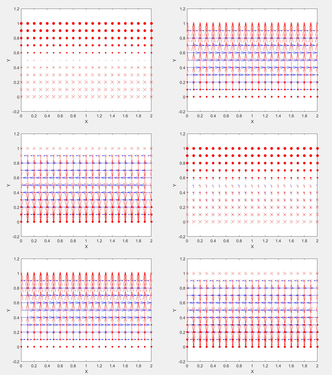
Demonstration
Field Distribution of TE01 mode at Transversal Cross Section ( f = 2 fc )
Field Distribution of TE01 mode at Longitudinal Cross Section ( f = 2 fc )
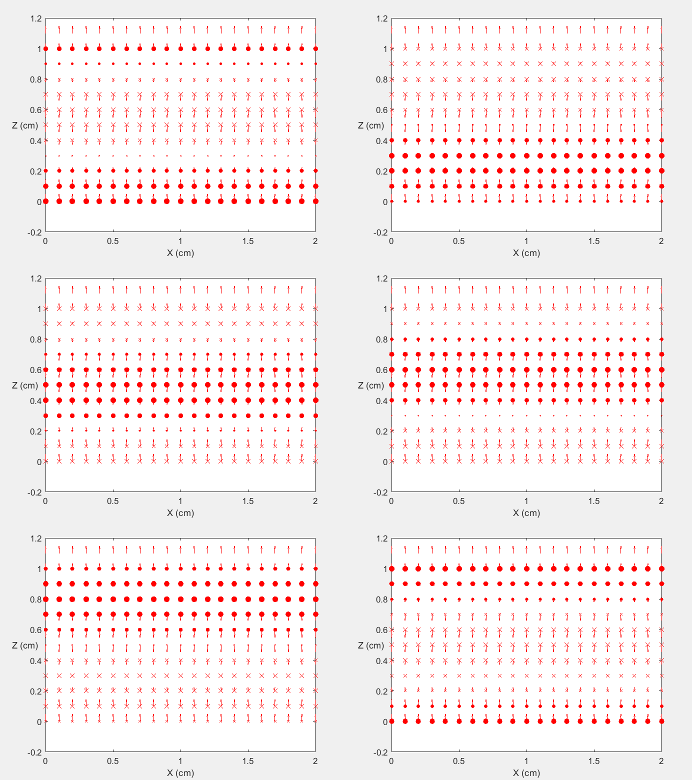
 |
 |
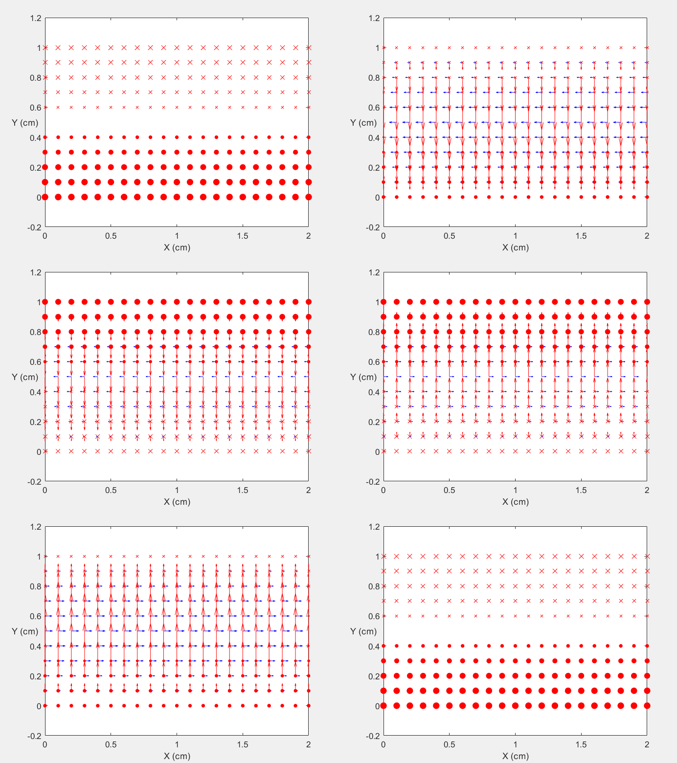
Field Distribution of TE01 mode at Transversal Cross Section ( f = 0.8 fc )
Field Distribution of TE01 mode at Longitudinal Cross Section ( f = 0.8 fc )
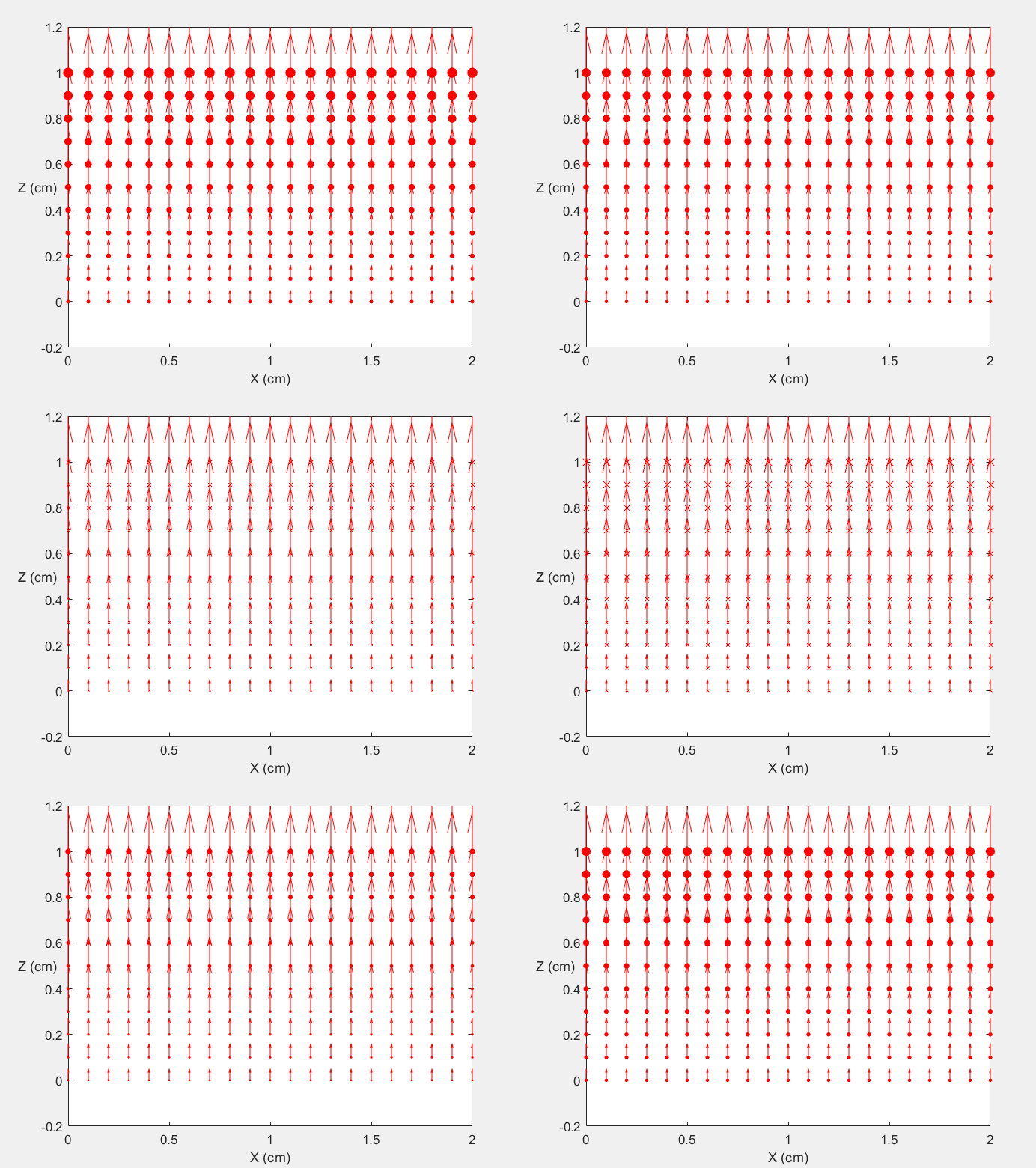
 |
 |
Field Distribution of TE10 mode at Transversal Cross Section ( f = 2 fc )
Field Distribution of TE10 mode at Longitudinal Cross Section ( f = 2 fc )
 |
 |
Field Distribution of TE10 mode at Transversal Cross Section ( f = 0.8 fc )
Field Distribution of TE10 mode at Longitudinal Cross Section ( f = 0.8 fc )
 |
 |
Field Distribution of TE11 mode at Transversal Cross Section ( f = 2 fc )
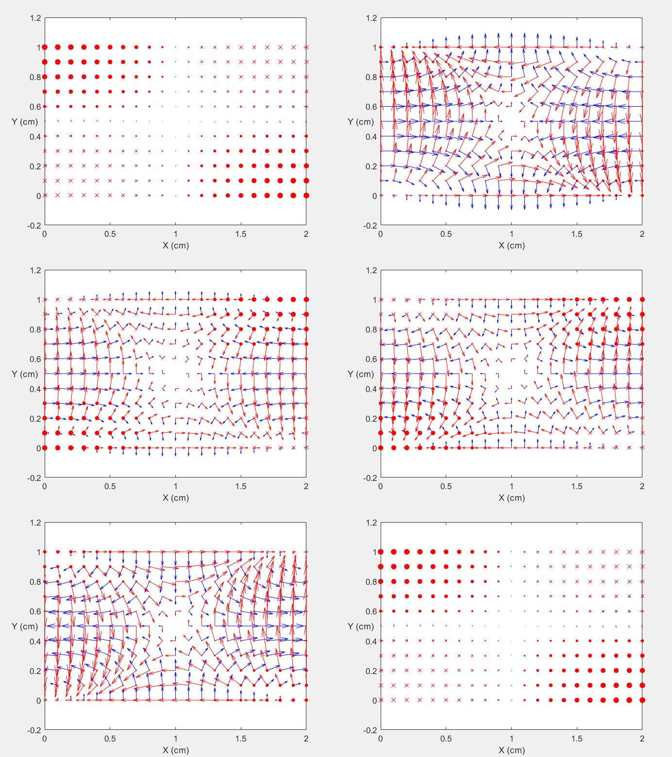
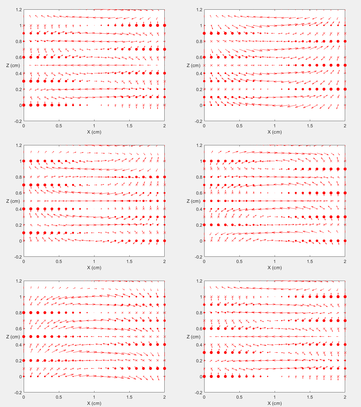
Field Distribution of TE11 mode at Longitudinal Cross Section ( f = 2 fc )
 |
 |
Field Distribution of TE11 mode at Transversal Cross Section ( f = 0.8 fc )
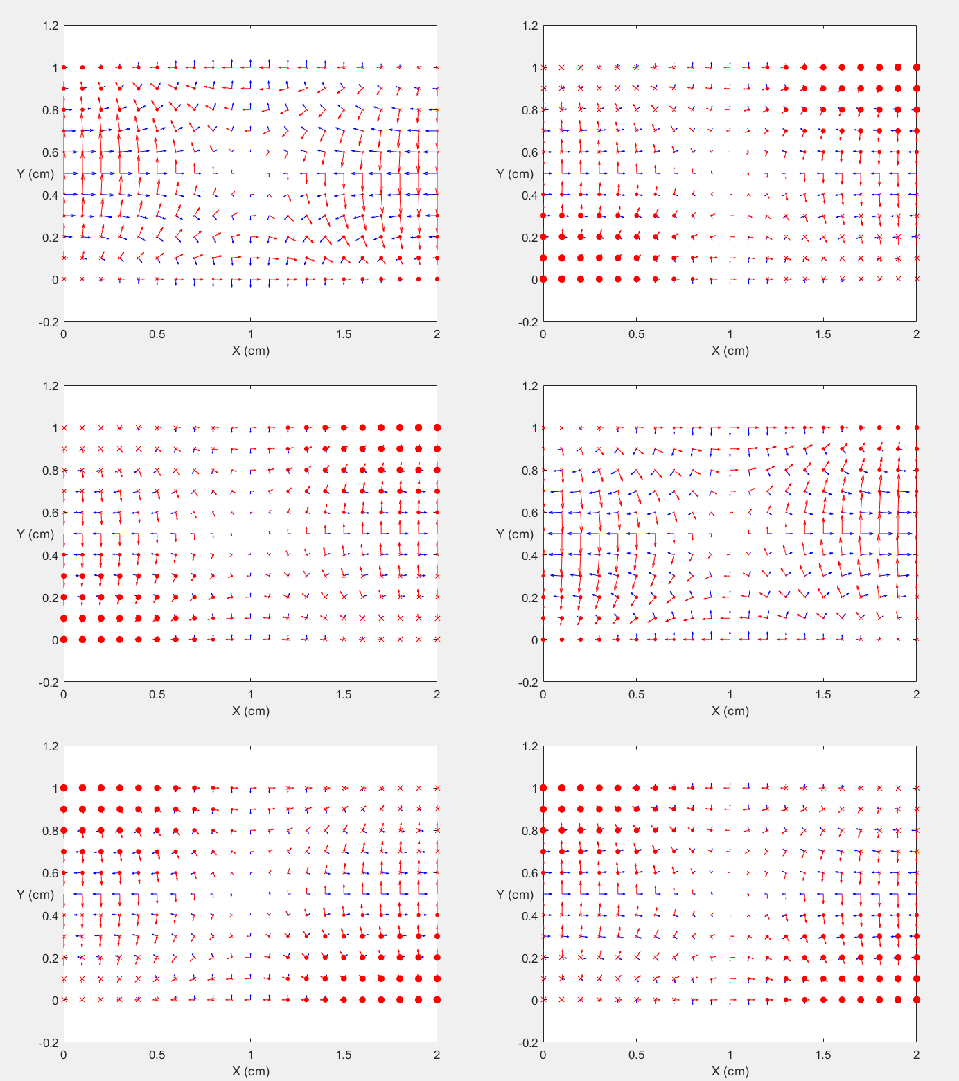
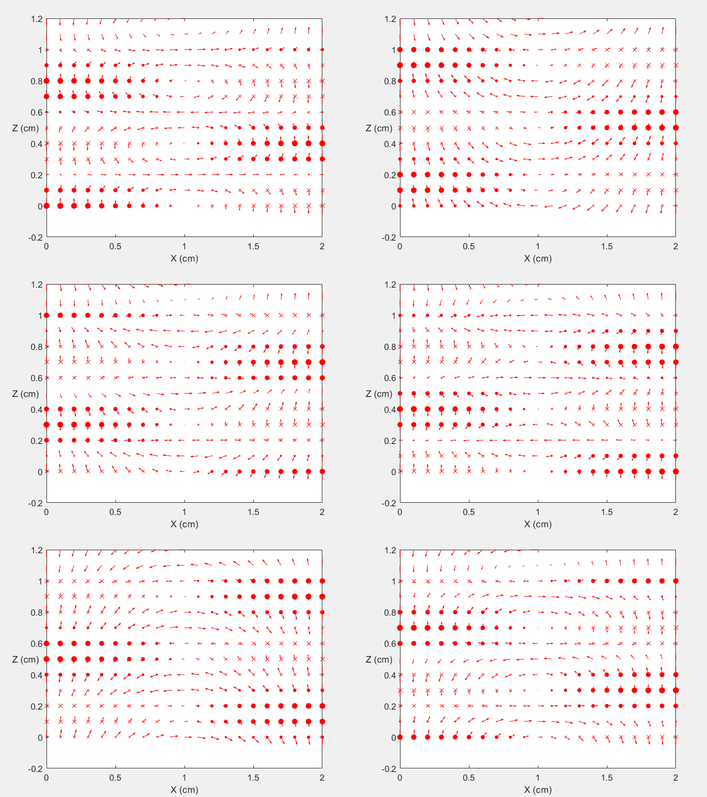
Field Distribution of TE11 mode at Longitudinal Cross Section ( f = 0.8 fc )
 |
 |
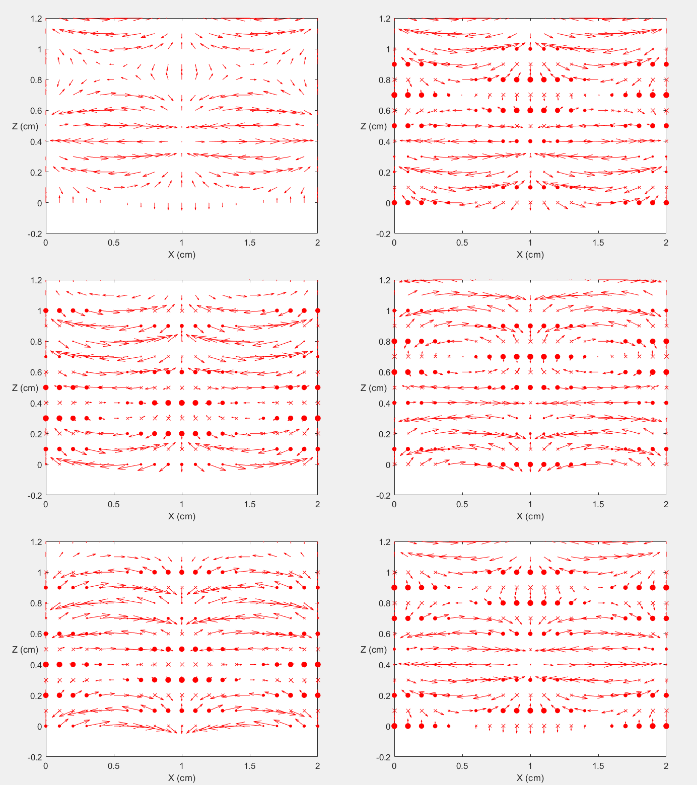
Field Distribution of TE21 mode at Transversal Cross Section ( f = 2 fc )
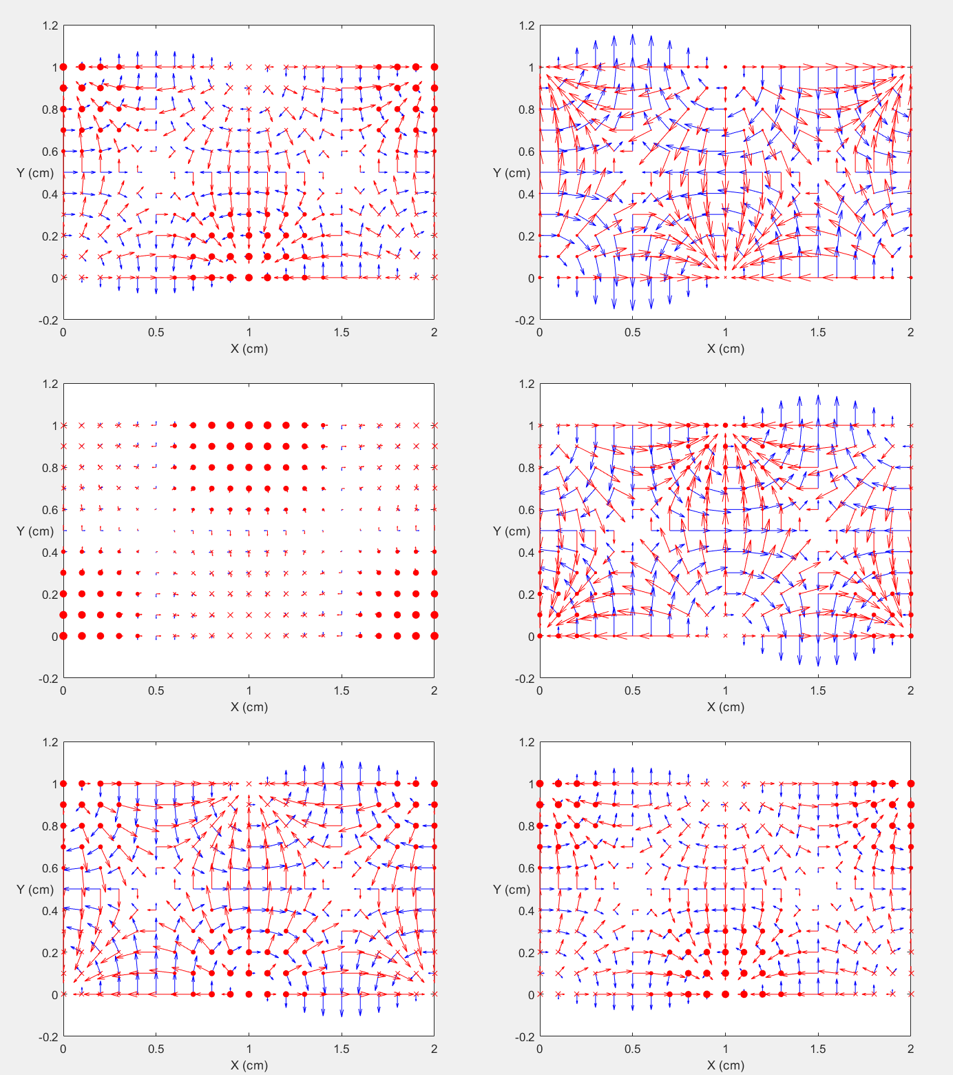
Field Distribution of TE21 mode at Longitudinal Cross Section ( f = 2 fc )
 |
 |
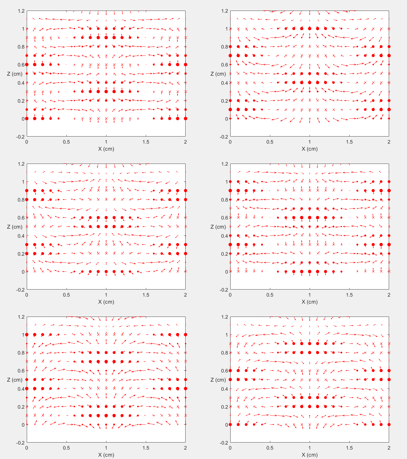
Field Distribution of TE21 mode at Transversal Cross Section ( f = 0.8 fc )
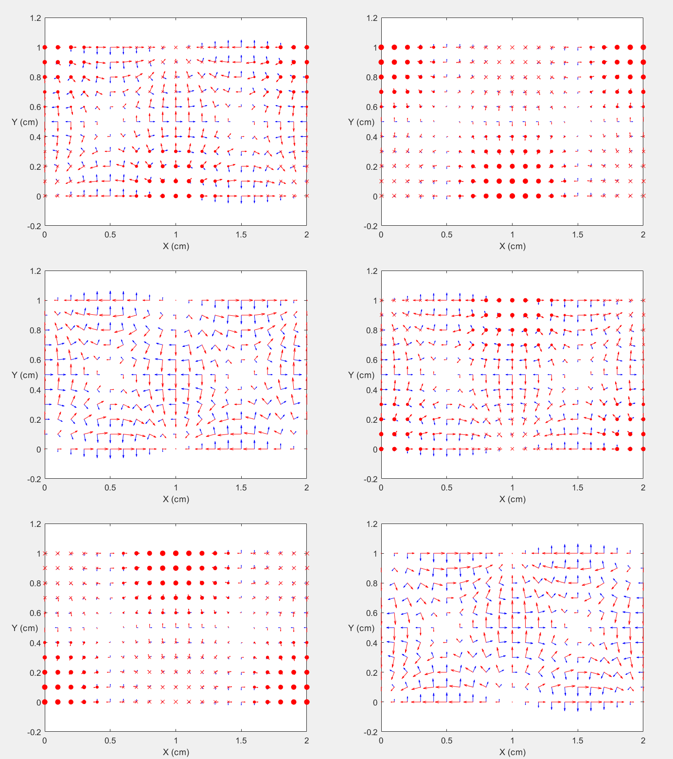
Field Distribution of TE21 mode at Longitudinal Cross Section ( f = 0.8 fc )
 |
 |