Double-Stub Matching
Authors : Shih-Hsuan Pan and Chou-Wei Kiang
Advisor : Jean-Fu Kiang
Background:
To achieve impedance matching at ![]() , namely,
, namely, ![]() . The admittance at
. The admittance at ![]() is
is
![]()
The associated reflection coefficient is

The reflection coefficient at ![]() is
is
![]()
The associated admittance is
![]()
The admittance at ![]() is
is

Note that b1 does not appear in the real part. First compute b2 by solving the equation for the real parts.
The real part of ![]() can be computed
from
can be computed
from ![]() and d1 to be
and d1 to be ![]() ,
,
![]()
The parameter b2 can be solved as

or

The parameter b1 can be solved from the equation for the imaginary
parts of ![]() as
as
![]()
where ![]() is the imaginary
part of
is the imaginary
part of ![]() , which is computed from
, which is computed from
![]() and d1.
and d1.
In particular, the input impedance ![]() of a short-circuited line of length l is
of a short-circuited line of length l is
![]()
The normalized input impedance of a
short-circuited line of length ls is ![]() , so that
, so that


Parameters used in the demonstration:
![]() = 0.6 + j0.8, Z0 = 50 W, l1 = 0.13483λ , l2 = 0.32726λ , d12 = 0.375λ , d1 = 2λ
= 0.6 + j0.8, Z0 = 50 W, l1 = 0.13483λ , l2 = 0.32726λ , d12 = 0.375λ , d1 = 2λ
Solution:
To find solution for plotting V-z graph and I-z graph that varies with time t, simply applying the background information is not enough. The detail steps are as follows:
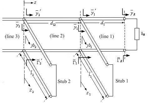
(1) Solve the matching problem directly by applying KVL and KCL at two nodes, where two stubs intersect with the main transmission line, respectively.
(2) Apply some of the background information, in order to reduce the complexity of the solution. We suggest that the lengths of two stubs, length of d12, length of d1, zR, Z0, and the magnitude of source voltage should be given first.
(3) There are total of 9 phasor variables, which are all magnitude of voltages at different sections (The input source voltage toward +z direction V+ should already be given).
(4) Note that the coordinate systems of stubs should be different with coordinate system of main transmission line, that is, there are at least 3 coordinate systems.
(5) There are total of 9 boundary conditions: 1 at the load, 1 at the short-circuited end of stub 1, 1 at the short-circuited end of stub 2, 3 at each intersection of stub and transmission line respectively (KVL, KCL)
(6) Use 9 boundary conditions to solve for 9 variables, and the solutions of currents and voltages in phasor form should be obtained. Transform solutions in phasor form (in frequency domain) into time domain solutions by multiplying ejωt, then taking the real parts.
Results:
(a) Voltage on the main line

(b) Current on the main line
(c) Voltage on the stub 1
(d) Current on the stub 1
(e) Voltage on the stub 2
(f) Current on the stub 2